Estimating Flow In Your System
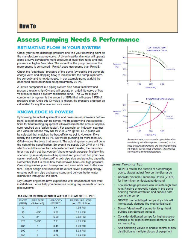
Check your pump discharge pressure and find your operating point on the manufacturer’s pump curve. A given impeller diameter will operate along a curve developing more pressure at lower flow rates and less pressure at higher flow rates. The more flow the pump produces the more energy is consumed – Point A uses less energy than Point B.
Check the “deadhead” pressure of the pump (by closing the pump discharge valve and stopping flow) to indicate that the pump is perform-15 ing correctly and is not damaged. In our example pump at right the deadhead pressure should be approximately 70 PSI.
A known component in a piping system also has a fixed flow and Flow (GPM) pressure relationship (Cv) and will operate on a definite curve of flow vs pressure called a system resistance curve. The Cv for a given component or system is the amount of GPM that will cause 1 PSI of pressure drop. Once this Cv value is known, the pressure drop can be calculated for any flow rate and vice versa.


Knowledge is Power!
By knowing the actual system flow and pressure requirements beforehand, a lot of energy can be saved. We frequently find that specifications for heat treating equipment will overestimate the amount of pressure required as a “safety factor”. For example, an induction scanner or a vacuum furnace may call for 200 GPM @ 60 PSI. A pump will be selected that matches the best efficiency point. However, if we satisfy the demand for 60 PSI we will be pumping far more than 200 GPM—more like twice that amount. The actual system curve will be to the right of the specification. So even if we supply 300 GPM at 41 PSI, which should be more than adequate for heat transfer, the manufacturer may point out that you don’t have enough pressure. Multiply this scenario by several pieces of equipment and you could find your new system seriously “undersized” in both pipe size and pumping capacity. Remember that it is mass flow that removes heat—not high pressure. Oversizing wastes pump horsepower and even adds heat to the system. Proper design and review at the outset saves pumping energy, ensures optimum pipe and pump sizing and delivers better water distribution throughout the plant.
Dry Coolers engineers have experience with thousands of heat treat installations. Let us help you determine cooling requirements on complex systems.
Maximum Recommended Water Flows Steel Pipe
| Flow (GPM) | Pipe Size (Sched 40) | Velocity (ft/sec) | Pressure Loss per 100′ of pipe |
|---|---|---|---|
| 10 | 1″ | 3.71 | 1.95 psi |
| 35 | 1-1/2″ | 5.52 | 3.61 psi |
| 70 | 2″ | 6.69 | 3.82 psi |
| 125 | 2-1/2″ | 7.71 | 4.03 psi |
| 200 | 3″ | 8.40 | 4.49 psi |
| 300 | 4″ | 8.68 | 3.33 psi |
| 600 | 6″ | 8.79 | 1.69 psi |
Some Pumping Tips
- NEVER restrict the suction of a centrifugal pump, always adjust flow on the discharge
- Consider Variable Frequency Drives (VFD’s) for intermittent or fluctuating demand
- Low discharge pressure can indicate high flow rate. Pinging or gravelly noises in the pump housing means cavitation and serious dam-age to the pump
- NEVER run centrifugal pumps dry – this will immediately damage the mechanical seal.
- Do not “deadhead” a pump for long – heat buildup can damage the seal
- Consider dedicated pumps for high pressure circuits or for high intermittent demand, such as quenching
- Add balancing valves to enable control of flow distribution to multiple pieces of equipment