Your Cooling Tower is a Giant Air Washer!
The fan on a cooling tower draws in thousands of cubic feet per minute of outside air that contains sand, dust, insects, and fibers from vegetation. These airborne contaminants mix with the process cooling water and eventually these suspended particles find their way into heat transfer surfaces. After a period of time these surfaces become fouled and insulated causing equipment to run hotter until replacement or repair is necessary.
By removing 98% of these suspended solids mechanically, fouling is greatly reduced and chemical water treatment and bleed from the system can be reduced significantly.
Full stream filtration protects the system from dirt deposits such as winds blowing over newly plowed fields, chunks of scale eroding from steel pipe or foreign deposits encountered by adding new piping to an existing system.
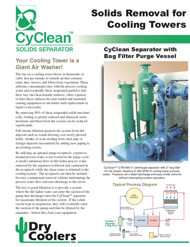
By utilizing an optional purge receptacle, expensive treated process water is not wasted in the purge cycle. A small continuous flow of dirt laden process water removed by the separator is filtered and contained in the receptacle while the clean water is returned to the cooling system. The receptacle can then be isolated for easy contaminant removal without interrupting the process water flow and zero discharge to the sewer.
The key to good filtration is to provide a system where the dirt laden water can enter the suction of the pump that discharges into the CyClean™ separator for maximum filtration of the system. If the solids can be kept in suspension, they will eventually enter the suction of the pump and then be filtered by the separator—before they foul your equipment.

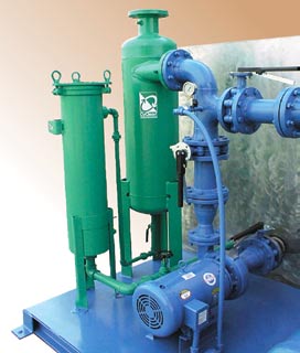
for full stream cleaning of 350 GPM of cooling tower process
water. Features zero water discharge and easy solids removal
without interrupting system operation.


CyClean Centrifugal Separators:
REDUCE Fouling on heat exchangers
REDUCE Chemical water treatment cost
REDUCE Water usage (less tower bleed required)
- Works by Centrifugal Force
- No Moving Parts
- No Wasted Water – Zero Discharge
- Removes 98% of Suspended Solids
- Full Stream Protection
OPTIONAL FEATURES
- Bag Filter Purge Receptacle
- Clean Out Port
- Differential Pressure Gauge
- Stainless Steel or other Alloy Construction
CAPACITIES and DIMENSIONS
Cv ratings are based upon water. Pressure drop at a given flow in psi = (gpm/Cv)2. Dimensions are subject to change. Consult factory for certified drawings. Consult factory for fluids other than water or for larger sizes which are available upon request.
| CyClean Inlet/Outlet Flow Range Model Size GPM |
Dimensions (Inches) | Cv GPM |
Weight lbs. | ||||||
| A | B | C | D | E | |||||
| CY-150 | 1 1/2” NPT | 45 – 75 | 30 | 7 | 2 1/2 | 6 | 3/4” NPT | 26 | 65 |
| CY-200 | 2” NPT | 60 – 105 | 34 | 7 3/4 | 4 | 8 | 1” NPT | 35 | 100 |
| CY-250 | 2 1/2” FLG | 85 – 160 | 34 | 8 1/4 | 4 | 8 | 1” NPT | 48 | 120 |
| CY-300 | 3” FLG | 160 – 300 | 40 | 11 3/4 | 3 5/8 | 12 | 1 1/2” NPT | 97 | 170 |
| CY-400 | 4” FLG | 260 – 450 | 43 | 14 1/4 | 4 | 14 | 1 1/2” NPT | 152 | 290 |
| CY-500 | 5” FLG | 340 – 600 | 50 | 15 1/4 | 3 1/2 | 14 | 1 1/2” NPT | 193 | 340 |
| CY-600 | 6” FLG | 600 – 1100 | 57 | 16 1/4 | 3 3/4 | 15 | 1 1/2” NPT | 352 | 410 |
| CY-800 | 8” FLG | 1050 – 1800 | 69 | 17 3/4 | 4 3/4 | 17 | 2” NPT | 590 | 650 |
| CY-1000 | 10” FLG | 1550 – 2650 | 82 1/2 | 20 | 5 5/8 | 19 | 2” NPT | 880 | 930 |
| CY-1200 | 12” FLG | 2050 – 3500 | 96 | 22 | 5 5/8 | 20 | 2 1/2” NPT | 1175 | 1240 |
| CY-1400 | 14” FLG | 2800 – 5000 | 104 | 23 | 8 | 23 | 2 1/2” NPT | 1610 | 1600 |

